During my internship at HOPE Technik, I was enamored by the CNC machines in the workshop. Something about the speed, precision and capabilities of these machines piqued my interest greatly. Naturally, I had to build one for myself! A project that took over 2.5 months to materialise, it can be broken down into its 3 different component types: mechanical, electrical and software.
Mechanical
Frame
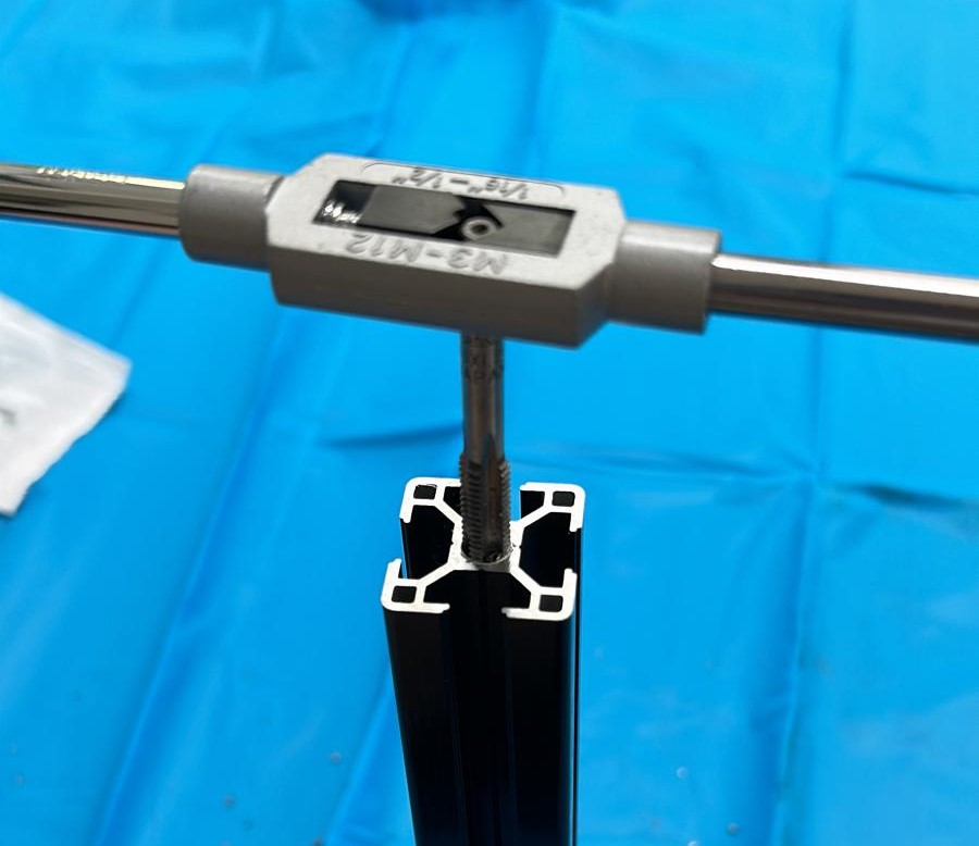
Given that the project was completed at home, I had to work with the limited tools and materials available to me (basically a 3D printer and drill set). I opted for a pure 3030 aluminium extrusion build, allowing me to minimise tooling required without compromising on rigidity. I mostly utilised corner brackets with M6 T-nuts to hold the extrusions together. For corner connections that did not have sufficient space to fit a corner bracket, I purchased an M8 tap set to fasten the extrusions with an M8 bolt.
Moving Parts
Before embarking on the project, I had the luxury of receiving an old set of linear rails and lead screws from a friend.
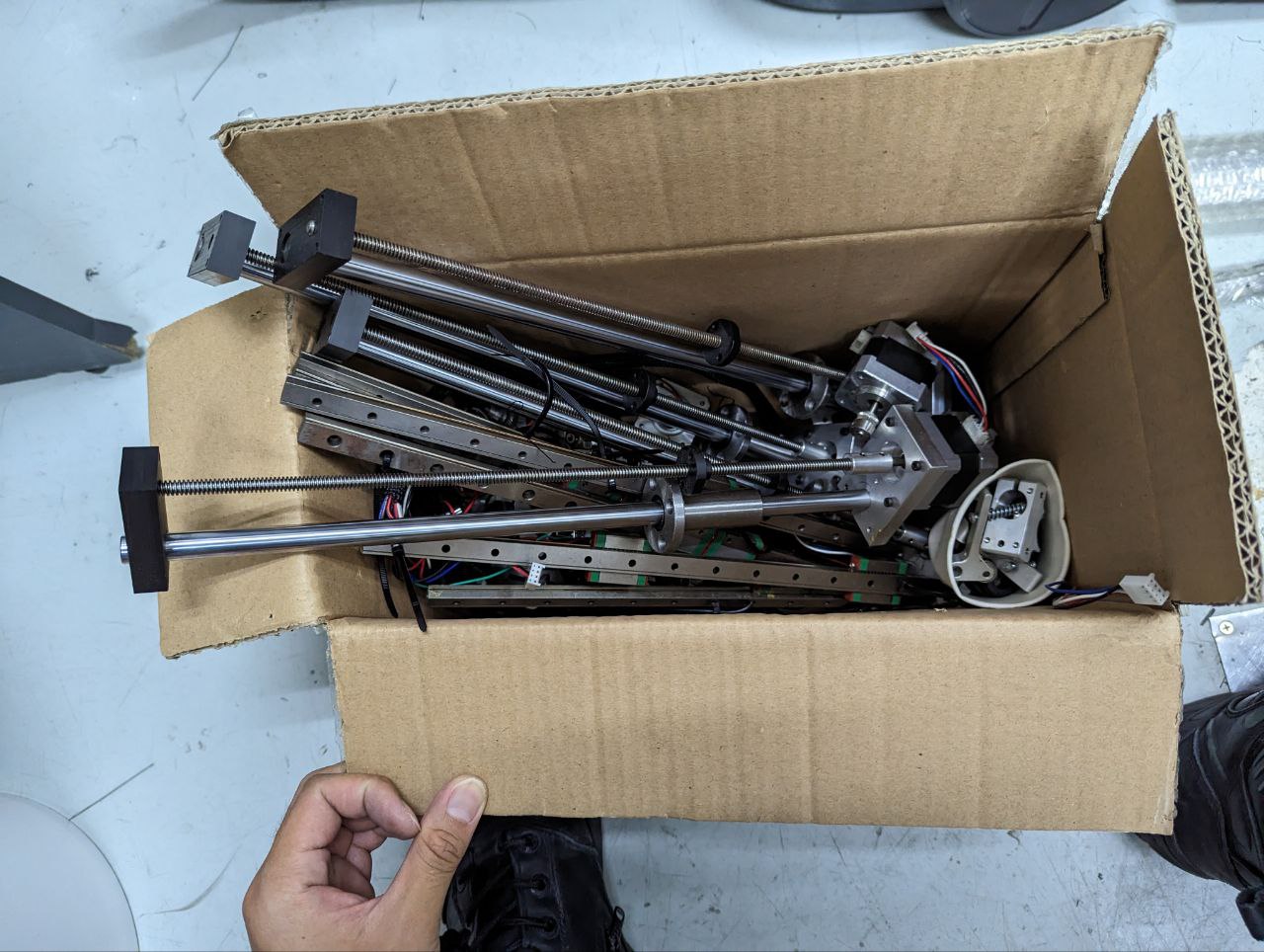
As the lead screws measured in at around 300mm, I used this limit to set the working area of my machine. I also had to design mounts to integrate my rails and screws into the system. Seeing some CNC mill builds created with 3D printed parts, I decided to take a bet on PLA and use 3D printed mounts. I utilised the M6 T-nuts and M3/4 heat set inserts to integrate my mounts.
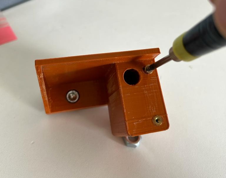
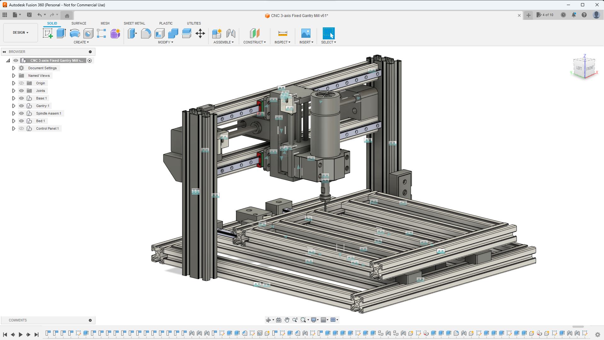
Since it was a relatively small machine, I also went with a fixed gantry system which would be easier to design. With all these considerations, I used Fusion 360 to design (CAD) the entire mill design as seen at the start of the section. The CAD of the mounts were then 3D printed out for use.
The biggest mechanical challenge for this project was ensuring all 3 axes were aligned squarely. Less than a degree of deviation from the expected linear rail arrangement could cause the machine to bind and lock up, or produce incorrect cuts. To mitigate this, I made adjustments with measurements from a vernier caliper and followed this method to prevent binding.
Software
The machine is given movement instructions using a programming language called G-code. After watching a few DIY CNC mill videos, I was pointed to an open source motion control software called GRBL that I could run on an Arduino Uno.
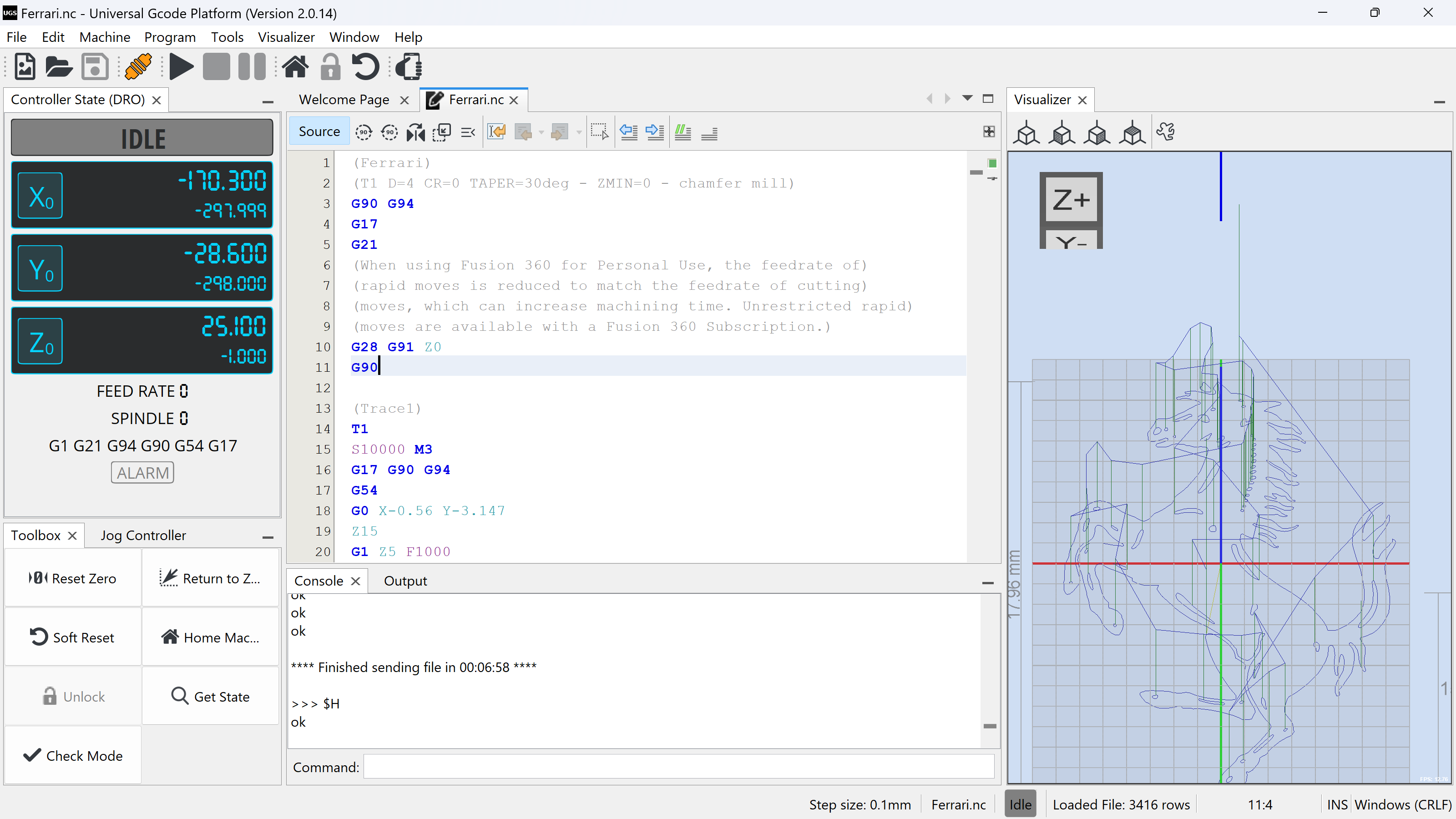
Since an Arduino Uno has limited memory and lacks a user interface, the machine is hooked up to a laptop running Universal G-Code Sender (UGS), where I could define machine settings and “drip feed” G-code without overwhelming the microcontroller.
For my project, I used GRBL 1.1 and UGS 2.0.14. Beside allowing me to run G-code on the machine, the combination of GRBL and UGS also allowed me to “home” the machine using limit switches. This gave me a fixed zero point that the machine could return to whenever it was powered on, providing consistency in between cuts.
Finally, when the machine was complete, I utilised Fusion 360 to CAD the desired cuts that I wanted to make, while creating the required toolpaths and G-code in its machining software (CAM).
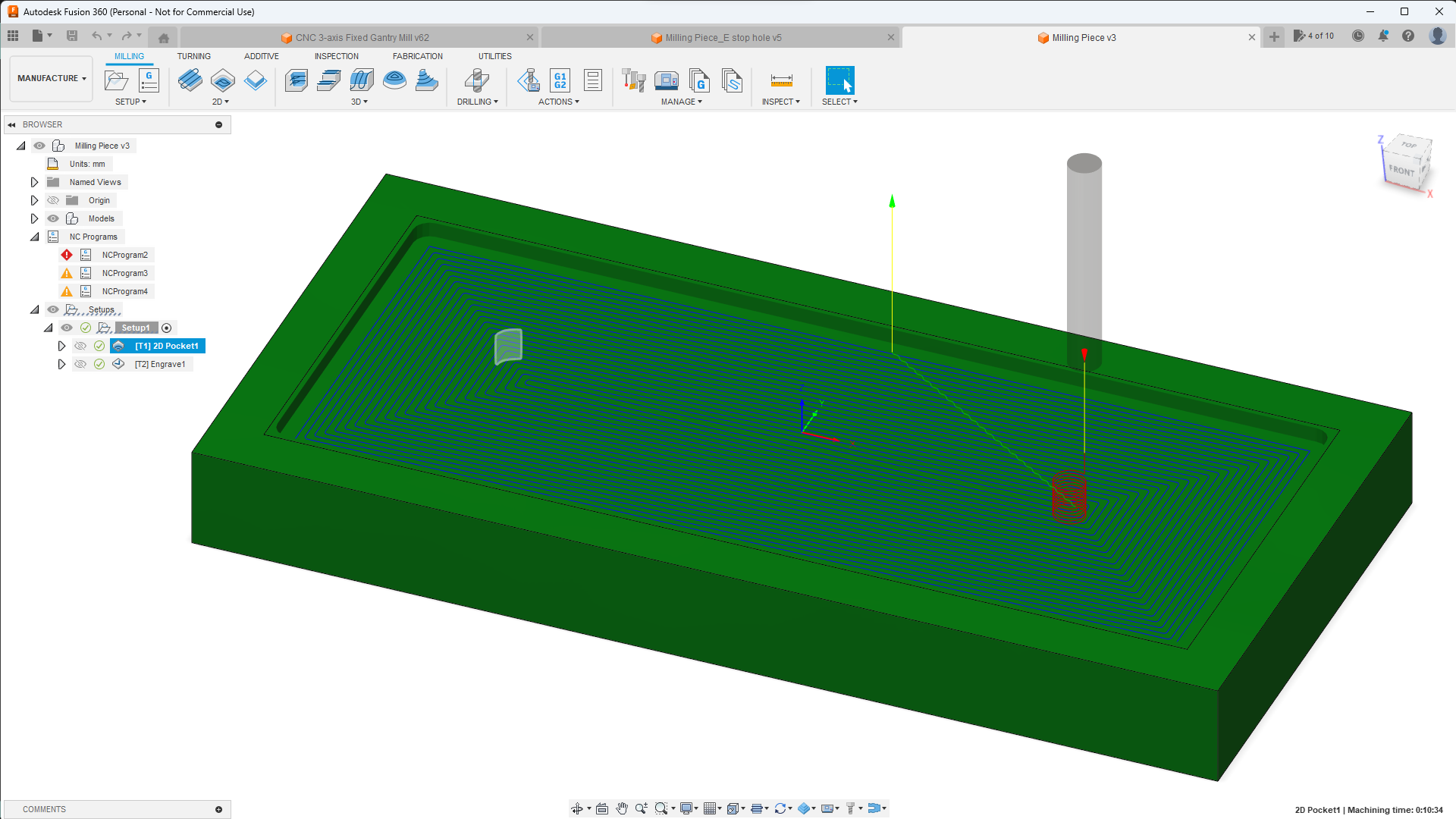
Overall, the software component of the machine was fairly uncomplicated. The biggest challenge was ensuring a precise calibration of my machine, where I needed to ensure that the software expected travel distance aligned perfectly with the actual machine travel distance (down to the .1mm).
Electrical
Electronics
As mentioned in the previous section, I decided to go with an Arduino Uno as the machine’s microcontroller. The Arduino was expected translate the recieved G-Code into signal pulses for the stepper motors (precision motors used to control the 3 axes).
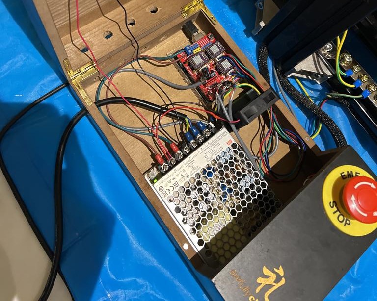
These signals would then be used to power the motors using a DRV8825 drivers, which drew power from a 24V power supply unit (PSU). When installing the drivers, I made sure to set the current limit of the motors accurately (not before frying a few of them oops).
I purchased a CNC shield which greatly streamlined the process of stepper motor control and limit switch wiring, allowing me to focus my attention on wiring.
Wiring
For wiring tools, I mainly relied on a ring terminal crimper and a small solder to connect all my electronics together. This proved insufficient, as there were other crimping connections required for the project. To circumvent this, I wire spliced and soldered my cables to pre-existing connectors using a rat tail splice.
Electromagnetic Interference (EMI)
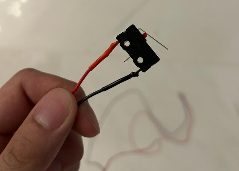
EMI is one of the biggest issues that CNC mills experience in the electronics department. When wiring my limit switches, I decided to go with a Normally Closed (NC) configuration (as seen in the picture above) to minimise false positives due to electromagnetic interference (EMI).
In spite of this, after setting up my machine for the first time, I realised that my limit switches were still receiving false positives, possibly from both the stepper motors and the spindle motor (the motor that drills). I also noticed that my z-axis stepper motor was drifting on its own during cuts, another symptom of EMI.
After going through the 5 stages of grief, I swapped out all my limit switch and z-axis stepper motor wiring with shielded cables. This solved my issue completely, but caused me a whole world of pain.
Grounding
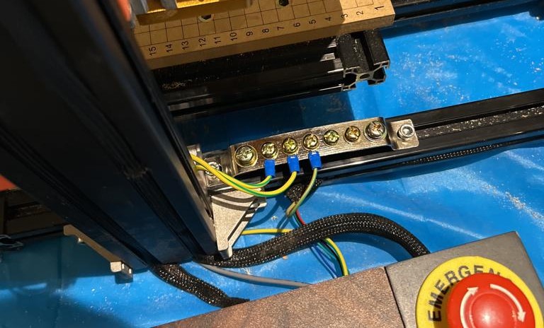
As a final measure to improve reliability and ensure that there is no unsafe accumulation of static electricity, I grounded all carriages and frames on the machine to the Potential Earth through my PSU. I achieved this by following the guidance of this post.
Learning Points
Through this experience, I had the opportunity to sharpen my CAD skills, where I had to measure, design and assemble a large array of moving parts. Working with CAM, I picked up basic 3-axis machining toolpaths, while learning a lot about the different milling bits and how they operate.
My biggest learning area would be in the electronics department, where I learnt the significant impact that EMI can make, and delved deeper into the concept of grounding. It was also fun honing my skills in crimping, wire splicing and soldering.
Finally, the procurement process for this project was challenging, tedious and truthfully, downright messy. It was my first taste of crafting a realistic bill of materials (BOM), and I ended up making countless orders due to poor consolidation.